extreme position

*
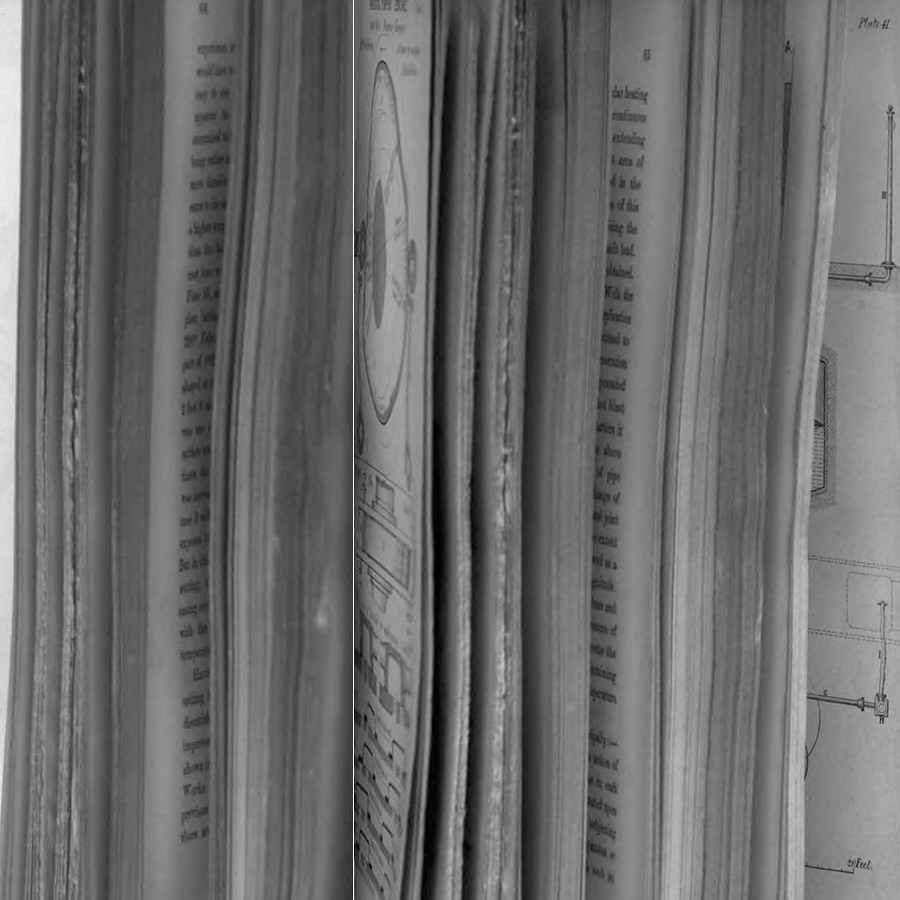
Plate 13. Horizontal Pumping Engines. Crystal Palace Pumping Engines
(two failed attempts at scanning same, here combined and cropped)
ex Edward A. Cowper (1819-1893 *, **). "Description of Two Pair of Horizontal Pumping Engines." Proceedings of the Institution of Mechanical Engineers (London, 1858) : 46-62
University of Wisconsin, Madison copy; digitized December 4, 2008
unobstructed view of plate here
illustrating p 52, from which —
The outline of the cam is made of such a shape as to hold the valve stationary in four positions in each revolution, as shown in the diagrams Nos. I., II., III., and IV.; and it will be observed that the valve stands still in these positions half the total time of each revolution. The whole travel of the valve is 6 1/4 inches; it is moved first 2 1/4 inches from its extreme position, from No. I. to No. II. (or No. III. to No. IV.), to cut off the steam at 1/3 of the stroke of the piston, and then remain stationary with the exhaust 1 1/2 inch open until close to the end of the stroke, when the valve is moved the remaining 4 inches of its travel, from No. II. to No. III. (or No. IV. to No. I.), thereby opening the exhaust and opening the opposite port to the steam... ¶ The curves of the cam are arranged so as to move the valve at each portion of its travel with a uniformly accelerated motion during the first half of each movement, and a uniformly retarded motion during the latter half... ¶ This valve motion the author has found to work with complete success; and whilst great economy of steam is obtained, the expense of a separate expansion valve is avoided; but in cases of very quick running engines the cam motion might be objectionable.
The plate and preceding discussion are a good introduction to the memory/control function of cams.
18 January 2014
tags: Edward A. Cowper; cams; engines; fore edge; memory; steam